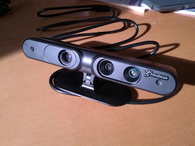
My previous post was a quick update about building a custom PC for logging purposes. This was going well until I came to actually trying to log some data. Using two
+Point Grey Research cameras and the Microsoft Kinect (
+Kinect for Developers) I quickly found the problem again that prompted me to build the logging PC.
Let me rewind.... In the post (
http://what-the-pixel.blogspot.co.uk/2013/03/data-collection-with-wall-e-v00001.html) I outlined the set-up of the logging robot to capture stereo images and Kinect ground truth. Using my main development laptop (
+Samsung) I was able to log stereo images, point cloud data and kinect RGB images no problems. I transferred the logging code over to the ruggedised
+Dell laptop. Hmmm this is where I ran into problems... it didn't work. The
+Point Grey Research cameras were only returning partial images. I concluded that the
+Dell laptop had all of its USB ports on the same bus and it couldn't cope with the data rates, bugger!
That brings me to the dedicated logging PC. It's small, low power, capacity for extra cards via the PCIe and 2x mini-PCIe ports, not to mention the plethora of 4x USB3.0 ports on the rear I/O plate and the 5x USB2.0 headers on the motherboard. Coupled with 6GB of RAM a Core i5 (3470-T @ 35W I think) and a decent, yet smallish, 320GB SpinPoint, this was looking like a tasty little logger!
So back to the original problem... it still didn't work! After some reasearch I found this nugget of information.
- If the Kinect is plugged into a USB 3.0 port, plug it into a USB 2.0 port instead.
- Make sure the Kinect is plugged directly into a USB 2.0 port, and not through an external USB hub.
- Since a Kinect requires at least 50% of the USB bandwidth available, make sure that the Kinect does not share the USB controller with any other devices.
So after finding that, I left the
+Point Grey Research cameras plugged into two USB3.0 ports on the I/O plate and switched the Kinect to one of the USB2.0 motherboard headers. Blast! it still wasn't working. I'll try the other header.... nope still rogered! There's 1 left, not holding out much hope but lets give it a shot.... finally, it's working! I'm not entirely sure why this header would be a different controller, but it's working at the moment which is progress.
If I have time next week I might throw linux onto it and see if it's a OS limitation that I'm banging my head against.
Here are some pics of the USB header mods I made to the case in order to added more ports.
 |
| The mounts on the USB port perfectly aligned with the case holes. Just a shame I scratched the case with the +Dremel Europe as I was cutting... I'm sure it won't be the only war wound it gets. |
 |
| This one is now labeled as the Kinect port! |
 |
| Thought I'd add RS-232 while I was at it, seeing as the robot can be controlled via it and the motherboard had a header for it. |
 |
| The only Kinect friendly header.....WHY!?... |
 |
| Back together (again) but with upgrades :) |


.png)
