Pages

Sunday 3 February 2019

Home Automation Multi-sensor

Overview

In this project I use a commercially available PIR (passive infrared) sensor, the same typically found in home alarm systems, to make a home automation multi-sensor by equipping it with an ESP8266.


Motivation

There are many project quality PIR sensors available for use with Arduino-like devices such as this...
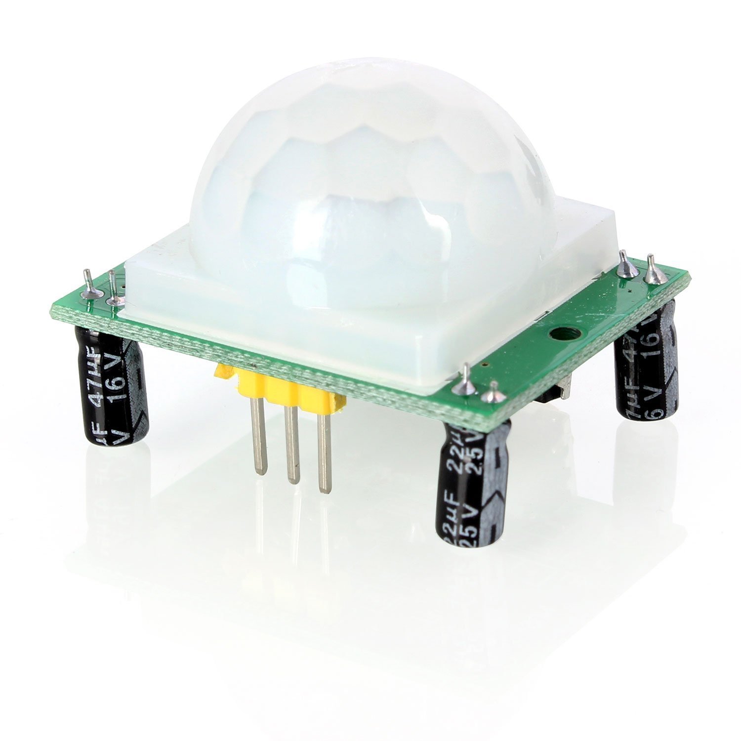
https://amzn.to/2GGhyPs

In fact, I used one of these for a previous project with an Arduino, it worked very well. They have configurable sensitivity levels and timeouts.
It was an obvious choice to use one when making a home automation trigger.
However... after building a test device on breadboard with an ESP8266 I found there were a lot of false alarms. After a bit of research I found others had similar issues, it appears this, and similar units, have poor RF interference protection resulting is false triggers.

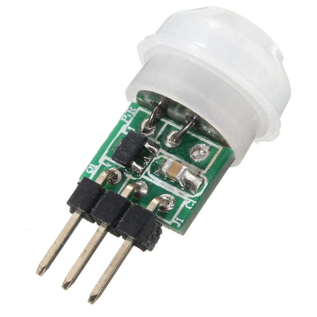
I have come across others that used this PIR with better RF protection against false alarms.


I decided against using this for my home automation sensor for two reasons;
  1. It's still hobby grade. By this I mean it's susceptible to change design at any time with no requirements to adhere to any standards.
  2. I still need to design/make/print a case


Solution

Use a commercial sensor. This perfectly answers the two points above.
  1. Commercial grade. This has to conform to alarm grade standards so it's RF shielded, designed to operate 24/7 in home environments.
  2. It has a purpose designed case, mount, IR window, etc.

The Build

I had no preference for PIRs so just went for any alarm sensor that was at the lower end of the price spectrum and looked large enough to accomodate an ESP8266. I went for the 
Honeywell IS312B as it is 'Pet Tolerant' and includes a 'Swivel Bracket' all for sub £12.

That'll do.

The first task is to work out how to interface with the PIR. Looking at the green edge connector along the top of the PCB, left to right we have T2, T1, NC, C, V-, V+


The obvious terminals are V- and V+ and reading the data sheet it says it uses 9 – 15 VDC, a nice wide supply voltage. I powered it up with a 12v bench supply to test it worked. It has about a 10 second warm up time before it's ready to start sensing. Getting the multimeter out and using the continuity mode it was pretty quick to find out that when the sensor is idle NC and C are a closed-circuit. When motion is detected NC and C go open-circuit.

I think T1 and T2 are tamper detection terminals, I'm not interested in this feature just now so didn't bother to characterise their behaviour.

Now we have the connections mapped we can move to task two, ESP8266 integration.
I have a drawer full of ESP8266 devices in various guises, NodeMCU, Wemos D1 Mini and bare 8266's in the 01, 07 forms. The bare forms like the 01 and 07 are great because they are tiny, however they lack the USB controller and power regulator so for development I just used the Wemos D1 Mini. 

It turned out the D1 fits perfectly under the PIR PCB. I mean perfectly, like it's designed for it. I didn't even bother fixing it in place, just used some tiny sticky foam pads on top of the D1 and used the compression from the PIR PCB when it's clipped into its mounting points.


The alarm state is just read using a digital read. C is held low by connecting it to V- (which is actually ground). A GPIO of the D1 is connected to NC and configured as an input with the internal pull up resistor enabled.

  pinMode (PIR_PIN, INPUT_PULLUP);

This means that when NC - C goes open circuit we read the internal rail voltage thanks to the pull up resistor. When NC - C is closed the input pin is pulled low.

I said at the start this was a multi-sensor. I simply added a DHT22 externally to the rear of the case, there are hundreds of articles and posts about using these so I won't rehash any of those.

All wired up!


Tip: Temporarily mount it while testing locations for best coverage.


That's pretty much it. I now have a PIR with a neatly integrated ESP8266. The USB port D1 is easily accessible should I want to flash new firmware onto the device. This is still a bit awkward to do, so I've configured the D1 to accept OTA (over the air) firmware updates.

Code can be found here https://github.com/oliver9523/IoT_Sensor

The Dollar Game

In this post I'll talk about how I created The Dollar Game app for Android using Unity 3D. This was inspired by the Numberphile video on the topic.


This ad-free game can be downloaded free from the Play store here.

As soon as I saw this video about the Dollar Game I knew I had to turn it into a game.
Where. To. Start.
There are three things I need to solve to create this game:

1 - Control logic
This is the mechanism for interacting with the nodes, sending/taking money, keeping track of which nodes are connected.

2 - Visuals
The graphical style, visual representation of the nodes, edges, balance and transactions.

3 - Game Logic
This is quite a biggy. This will be responsible for generating new random games, this in itself isn't difficult [create nodes, randomly connect nearest n nodes, distribute money]... the difficulty is I have to ensure that the level is solvable, nobody is going to be happy if the graph is impossible to solve.

Lets knock off task 2 first, the visuals. Seeing as numberphile inspired the app I thought I'd use their brown-paper look and a handwriting style font. The rest of the elements are in keeping with that style. Done.

Now to build the control logic.
//TODO Explain the approach and publish code


Easy

Medium

Hard


Weighted node connections indicate how many dollars will be transferred for each transaction.


IoT Audio Source Switcher [Part 2 - Software]

Recap

In Part 1 I outlined the hardware aspects of creating an IoT audio source switcher. In Part 2 I'll cover the software side of things.

Problem
To be able to remotely select the input audio source from a variety of devices.

Solution
Use network (WiFi / LAN) connections to send messages to enable control.

Architecture
When it comes to network communications there are a number of different ways to accomplish a task. The most common being HTTP calls to some predefined API e.g. http://server1.sky-map.org/search?star=polaris
This is great for sending requests for information, in this example we request the information for the star polaris and we receive XML encoded response. XML and JSON are common formats for communicating this type of information as they can both be parsed quickly and easily.
The HTTP approach also requires that we know the IP address of the device we want to communicate with. This can cause unnecessary extra work.

HTTP Scenario
Here we have deployed the audio switched with an HTTP endpoint that looks something like this...
http://192.168.0.123:8080/audio?source=1
This looks great, we can send commands from any device on the network. However, if we have several devices that are setup to control the audio switcher, then for some reason we need to change the IP address of the audio switcher, all the control devices have to be updated (or perform a search of the full IP range) in order to keep communicating. This might need another endpoint so that we can check what device we're interrogating e.g. http://192.168.0.x:8080/info. 
Another solution is configuring a local DNS server so we can address each device by a name, but that sounds like even more overkill.

Multiple Device Scenario
Let's say we want to extend our setup, now we want to turn on/off some lights when we switch source on the audio switcher. To extend the HTTP implementation we'd need to hit multiple URLs on multiple IPs and possibly send multiple parameters to the endpoints. 

Example:
Our Audio Switcher is on 192.168.0.123
We have light controller on 192.168.0.124
And a power plug on 192.168.0.125

Say we want to switch to source 2, turn off two lights and turn on the device connected to the power plug.

We might have to hit the following endpoints, something like
192.168.0.123/audio?source=2
192.168.0.124/off
192.168.0.125/on

That's 3 different IPs we need to manage and 3 different http endpoints. To make it reliable we'll need to make the IPs static or allocate them in the DHCP settings of the router. 

Now imagine trying to update this after deploying. Adding another device, changing IPs, adjusting the workflow. It's starting to get complicated and difficult to maintain.

Let me introduce something called MQTT.


MQTT

"MQTT is a machine-to-machine (M2M)/"Internet of Things" connectivity protocol. It was designed as an extremely lightweight publish/subscribe messaging transport."

Sounds promising doesn't it?

MQTT uses a publish/subscribe approach to delivering messages to devices. Without just regurgitating hundreds of other sites / YouTube videos that explain MQTT I'll just get to the crux of the matter.

Unlike our HTTP example that requires the controllers to directly send data to the audio switcher (at a known IP), we now tell the audio switcher to subscribe to a topic. The topic is a communication channel that any device can listen to and any other device can publish to.
In the case of the audio switcher it subscribes to "0/kitchen/av/a" where I've defined the topic hierarchy format as "{floor}/{room}/{device}/{property}".

However, we still need to communicate with a specific IP, but at least it's only 1. The MQTT broker or server that handles all the messages. This grunt work is performed by a Raspberry Pi.

Here's how MQTT would work in our multiple devices example.
The audio switcher subscribes to "0/kitchen/av/a" and receives the simple message of 1-4 that dictates which input to switch to.
Any controller devices simply have to publish to the same topic "0/kitchen/av/a" with the message 1-4 to set the source.
Now, if I want to control a second device, say a power switch to turn on the TV if the input of the audio switcher is '1'. I simply have to subscribe the power switch to the same topic "0/kitchen/av/a", the controller knows nothing of the power switch, we haven't had to update the controller with another API endpoint or IP address of another device to control.


Summary

I built an IoT audio source switcher with 4 stereo inputs and 1 stereo output. This will be used to switch the input of an audio amp. Sources are switched using relays to avoid any cross-talk or other components leaking noise into the audio path.
I'm using an ESP8266 to control the unit and provide wifi access. Communication is handled using the MQTT protocol whereby clients can 'subscribe' and 'publish' messages to 'topics'.

The switcher subscribes to a topic e.g. "0/kitchen/av". Other devices can publish to this topic "0/kitchen/av" and include a message, this could be JSON encoded e.g. {"set": "source", "value": "2"}. Any device subscribed to this topic will receive this message and can process it accordingly.
I can publish to this topic from anything, an app, console, or another ESP8266. In one example I show a simple button press on another ESP8266 publishing a message to select the next source.

All the MQTT messages are handled by a local server or 'broker' running on a Raspberry Pi. The local nature of this 'IoT' means it doesn't rely on any external internet connections, third-party services or companies (https://www.telegraph.co.uk/technology/2018/10/12/glitch-yales-smart-security-system-sees-brits-locked-homes/)