Pages

Wednesday, 26 June 2013

Logging Software Done! (Almost)

Ok, so it has been a while since my last post. I've been working on getting some robust logging software working on the logging PC. The software is designed to capture from multiple +Point Grey Research cameras at 1280x960 15fps, a +PrimeSense P1080 depth camera at 15fps, a Phidget IMU and a GPS receiver.

Spot the devices...
The outline of the program is a multithreaded logger that uses 4 CPU threads (done with OpenMP)
Thread 0 - Point Grey image acquisition and writing data to disk
Thread 1 - Primesense P1080 Depth and Colour image acquisition
Thread 2 - Read new Phidget data
Thread 3 - Read new GPS data

The most important part of the data is the multi-viewpoint camera data from the Point Grey Cameras as synchronisation between these images is key to accurate reliable 3D reconstruction. As soon as all cv::Mat objects from each camera have returned, Thread 0 writes the image data from each camera as well as writing the image data from the primesense camera and logging the phidget and GPS info to CSV files.

A neat feature of the logger is the dynamic delay function that aims to keep a maximum frame rate.
A timer is started at the beginning of image acquisition and stopped at the end of all the file writing. If this processing time is less than the desired frame rate of 66.67ms (15fps) then a dynamic delay is calculated simply as SleepTime = MAX(DesiredDelay-ProcessingTime,2); cv::waitKey(SleepTime); This dynamic delay means the program doesn't query the camera faster than it's configured for and gives us a nice steady frame rate. The MAX(n,2) protects against -'ve' time values and means it always pauses for at least 2ms to allow for video buffer to draw to frames to the screen. Obviously if the ProcessingTime is >= DesiredDelay then it is not possible to obtain the selected frame rate and the program just runs as fast as it can.

There is still a problem that is unresolved. The USB GPS receiver appears to flood the USB bus. Without the GPS connected, two USB Point Grey FireFly cameras happily work at 1280x960 15fps. When the GPS is added to the system it causes errors on the bus causing frames to be dropped. Now the really odd thing is these errors only appear to happen when the cameras auto adjust exposure. Fixing the shutter and gain values programmatically solves the issue. However this isn't a viable solution as the cameras are going to be mounted on a vehicle that will be driven through scenes that have wildly varying lighting conditions.

This image shows the output of three different cameras with identical fixed shutter and gain values. The top left is the high spec Flea2 and the top right/lower left are the lower cost FireFly cameras. It's interesting to note that the Flea2 has wider spectral sensitivity as it can see the structured light pattern from the PrimeSense camera.
Sort of good...
 In this one we can see a boat load of errors coming from cameras 1-2, the FireFly cameras.
...not so good...
 Here the camera shutter and gain values have been fixed independently from one another. While this looks good, it is not a solution due to the varying lighting conditions it will operate it.
...sort of good.
It is almost complete. Just waiting to get a RS-232 GPS device to remove the USB bus from the equation and hopefully that'll just work...


Friday, 31 May 2013

Getting started with OpenMP

In the previous posts, about creating logging software for the boat trial, I mentioned the fact we were logging GPS and stereo images. This was done using OpenMP to parallelise the processing so that the program wasn't hanging around for a GPS update causing delay between image samples.

This is a quick guide on how to get OpenMP going.

My first mistake was thinking it was something that needed to be installed and configured. It's just a switch in Visual Studio 2010. Go to the project properties page. C/C++  > Language > OpenMP Support > Yes.


Now you'll be amazed how easy it is to get a simple program working that uses two cores...Here's a snippet from the logger that capture GPS data using 1 core and images from a camera using the other. I've highlighted the important lines of code and briefly outlined what their functions are.

#include <iostream>
#include <stdio.h>
#include <string>
#include <Windows.h>
#include "SerialGPS.h"
#include <omp.h>

#include <opencv/cv.h>
#include <opencv/highgui.h>

using namespace std;

int main( int argc, char** argv )
{  
  //set up the com port 
  SerialGPS GPS("COM6",4800);
  SerialGPS::GPGGA GPSData={};
  
  if (!GPS.isReady()) { return 0;  }
  cout << "GPS Connected Status = " << GPS.isReady() << endl;
  
  int gpsReadCounter=0;
  
  //create the video capture object
  cv::VideoCapture cap1;
  cap1.open(0);

  cv::Mat Frame;
  
  //define the shared variables between threads
  #pragma omp parallel sections shared(GPSData) {

    //////// FIRST CPU THREAD ////////
    #pragma omp section
    {
      for (int i = 0; i<100; i++) {
        cap1 >> Frame;
        cv::imshow("Cam",Frame);
        cv::waitKey(33);
        cout << "   GPS Data Time = " << GPSData.GPStime << endl;
      }
    }

    //////// SECOND CPU THREAD ////////
    #pragma omp section
    {

      for (int i = 0; i<100; i++) {
        if (GPS.update(GPSData, FORCE_UPDATE)) {
          cout << " T=" << GPSData.GPStime << " La=" << GPSData.Lat << " Lo=" << GPSData.Lon << endl;
        } else {
          cout << "Error Count = " << GPS.getErrorCount() << "  ";
          GPS.displayRAW();
          cout << endl; 
        }
      }
    }
  }
}


- Make sure to #include <omp.h>
- The line #pragma omp parallel sections shared(GPSData) enables the data structure, GPSData, to be accessible from either thread.
- The lines #pragma omp section define the code that is to run on an individual thread
- GPSData gets populated from the call GPS.update(GPSData, FORCE_UPDATE)
- Since we initialised all the values to 0 with SerialGPS::GPGGA GPSData={}; it doesn't matter if the camera thread gets to reading the data before the GPS update thread has populated the structure with any meaningful values.
- As soon as the the GPS thread receives a valid signal and updates GPSData accordingly this data is accessible from the camera thread.
- Note that while both threads loop while i<100, this i value is local to each thread. It's very likely that one thread will finish before the other as no synchronization is taking place here, we're just offloading the GPS updates so that it doesn't interfere with the image sampling and allows use to simply tag an image with the latest good GPS values.

This example broadly gives you an idea of how to use two threads and share a variable between them.

There's a handy OpenMP cheatsheet here (http://openmp.org/mp-documents/OpenMP3.1-CCard.pdf)

Wednesday, 29 May 2013

A "quick" Side Project

Since the last post I had my 9 month PhD review, it went pretty smoothly, passed with no problems :)
Shortly after I was asked by my project supervisor if I could help out quickly on another project. I'm always keen to work on a variety of projects.

The task was to simply pull together some already existing code to create a data logging program that logs stereo image from the +Point Grey Research bumblebee camera and log GPS positions, all this was going a remotely operated boat for the +Environment Agency.

I wrote a little C++ class to connect to a COM port and read off GPS data. This worked fine. The bumblebee however proved to be more of a challenge. I consulted a Masters student who had used it more than I had to obtain some code from him to read the images. The logging laptops are +Dell 6400 ATG's, theses are rugged laptops, perfect for use on the boat. Fresh installs of Win7 x64 were on these machines as they'd been hacked to pieces (not in the literal, more in the coding sense) in the past for various projects. So with the code working on a 32bit WinXP machine we ported the source over to +Microsoft Visual Studio (Link) in Win7 installed all the relevant +Point Grey Research drivers and..... nothin'.... 2 days went by of trying every sodding combination of drivers and libraries but none of the laptops were having any of it under x64. So we binned it and went back to trusty old XP.

We had hoped to get out onto the river yesterday (28/05/13) but a morning re-coding session to log grayscale stereo rectified images instead of colour un-rectified images, delays from +Leica Geosystems AG in obtaining a theodolite, problems with a bluetooth 5Hz GPS system that needs a power cycle if something tries to connect at the incorrect baud rate and not forgetting the British weather pissing it down all afternoon.

Student with his boat... finally.
As it was getting on for 6pm by the time everything was up and running we postponed the data logging day until tomorrow (30/05/13). Stay tuned for more....


Tuesday, 7 May 2013

Getting back to science...


So now the 9 month review report has been handed in I can get back to doing science. Before tackling the review report this is the stage I had reached. A 3D map of the DIP (Digital Image Processing) Lab at Cranfield University (albeit, a noisy one). It is a simple reproduction created using a stereo vision algorithm and visual odometry algorithm.

The process is...
- Create disparity depth map from stereo camera
- Calculate camera trajectory from the visual odometry
- Add point clouds to a global map with an appropriate offset calculated from the trajectory.

It's good... but there's lots of work to do yet...


The equation for converting disparity map values into real world depth is quoted in a ton of papers/books but I could not actually see where it was derived from so I worked it out for the review report for completeness. I'm posting it up on here so that it might help someone else.


Above is a diagram of the triangulation theory. We need to know a few parameters about the setup before we can triangulate from a disparity map image to real world depth.
We need :

- The focal length of the cameras (f) (ideally they would be the same)
- The baseline of the stereo rig (B)

So use the triangle ratios to get...
$\frac{P_{L}}{f}=\frac{X_{L}}{Z}\qquad\frac{P_{R}}{f}=\frac{X_{R}}{Z}$
...rearrange to get...
$X_{R}=\frac{ZP_{R}}{f}\qquad X_{L}=\frac{ZP_{L}}{f}$
...add them together to get the baseline...
$B=\frac{ZP_{R}}{f}+\frac{ZP_{L}}{f}=\frac{Z\left(P_{R}+P_{L}\right)}{f}$
...substituting disparity as d=Pl-Pr  by defining Pr  as a -ve ...
$Z=\frac{fB}{d}$

Disparity is calculated as difference in pixel locations for matched regions from left to right image (or the other way round depending on your ference camera). So Pr is shown as a -ve direction from the centre of the image plane so we define it as a negative.

Edit
10:35 22/5/13
I have no idea why but the latex equations have stopped rendering...
The addition of the javascript used to kill the Google plus comments box at the expense of the latex equations. Now it's just killing everything... arse.

10:38 22/5/13
oh no wait the comments box is back....wtf. 

14:09 1/7/13
It looks like using the dynamic page template in Blogger kills the latex script.

Monday, 29 April 2013

New toys...

Just a quick post. Received a new shiny +PrimeSense PS1080 Structured Light 3D camera today. 

This little fella is going to be mounted on the Robotic logging platform and replace the Kinect that's currently installed. The advantage with using this is instead of the kinect is:
1 - The mount it more sturdy
2 - It's a smaller
3 - Can be powered directly through the USB
4 - Hopefully it'll also use less bandwidth (see previous post for Kinect bandwidth issues http://what-the-pixel.blogspot.co.uk/2013/04/logging-pc-v2.html)

I was hoping to just plug-and-play with my previous logging software but alas it didn't work. I think +OpenCV needs to be recompiled for it to work.

I'll probably post a walkthrough on here when I come to getting this thing working.

Friday, 26 April 2013

Logging PC v2

My previous post was a quick update about building a custom PC for logging purposes. This was going well until I came to actually trying to log some data. Using two +Point Grey Research cameras and the Microsoft Kinect (+Kinect for Developers) I quickly found the problem again that prompted me to build the logging PC.

Let me rewind.... In the post (http://what-the-pixel.blogspot.co.uk/2013/03/data-collection-with-wall-e-v00001.html) I outlined the set-up of the logging robot to capture stereo images and Kinect ground truth. Using my main development laptop ( +Samsung) I was able to log stereo images, point cloud data and kinect RGB images no problems. I transferred the logging code over to the ruggedised +Dell laptop. Hmmm this is where I ran into problems... it didn't work. The +Point Grey Research cameras were only returning partial images. I concluded that the +Dell laptop had all of its USB ports on the same bus and it couldn't cope with the data rates, bugger!

That brings me to the dedicated logging PC. It's small, low power, capacity for extra cards via the PCIe and 2x mini-PCIe ports, not to mention the plethora of 4x USB3.0 ports on the rear I/O plate and the 5x USB2.0 headers on the motherboard. Coupled with 6GB of RAM a Core i5 (3470-T @ 35W I think) and a decent, yet smallish, 320GB SpinPoint, this was looking like a tasty little logger!

So back to the original problem... it still didn't work! After some reasearch I found this nugget of information.
  • If the Kinect is plugged into a USB 3.0 port, plug it into a USB 2.0 port instead.
  • Make sure the Kinect is plugged directly into a USB 2.0 port, and not through an external USB hub.
  • Since a Kinect requires at least 50% of the USB bandwidth available, make sure that the Kinect does not share the USB controller with any other devices.

So after finding that, I left the +Point Grey Research cameras plugged into two USB3.0 ports on the I/O plate and switched the Kinect to one of the USB2.0 motherboard headers. Blast! it still wasn't working. I'll try the other header.... nope still rogered! There's 1 left, not holding out much hope but lets give it a shot.... finally, it's working! I'm not entirely sure why this header would be a different controller, but it's working at the moment which is progress.

If I have time next week I might throw linux onto it and see if it's a OS limitation that I'm banging my head against.

Here are some pics of the USB header mods I made to the case in order to added more ports.

The mounts on the USB port perfectly aligned with the case holes. Just a shame I scratched the case with the +Dremel Europe as I was cutting... I'm sure it won't be the only war wound it gets.

This one is now labeled as the Kinect port!

Thought I'd add RS-232 while I was at it, seeing as the robot can be controlled via it and the motherboard had a header for it.

The only Kinect friendly header.....WHY!?...

Back together (again) but with upgrades :)

Tuesday, 23 April 2013

New logging PC

Quick update: just built a shiny new logging pic for the robot platform. It's based on an +Intel  DQ77KB board with an i5 CPU.

Tuesday, 16 April 2013

Car Camera Rig Construction

I'm coming up to the 9 month PhD review so a lot of my time is being spent writing a report for that. Although I spent the weekend writing a C++ class for serial GPS reading, it's a bit of 're-inventing the wheel' as there are libs available but it was actually easier just to write my own. I know it works with my GPS receiver and I'm getting exactly the data I want in the form I want. Nothing works as well as your own code. Once it's a bit more mature and extracting more information I'll pop it online somewhere, in the event someone else finds it's useful.

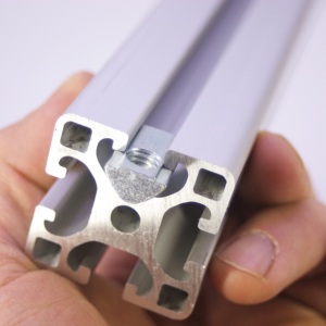
In the meantime I spent today redesigning the extruded aluminium frame that will hold the camera array and attach to a roof-rack. The items in question were purchased from http://www.valuframe.co.uk/. Just as an aside, one of the bars was a bit misshapen when it arrived, but we did receive an extra 2m of bar and a couple extra connectors...swings & roundabouts.


I initially constructed the frame in a symmetrical manner (see crude sketch). Two bars joined at the end with a 90° bracket and a corner plate (blue) to add rigidity, repeat for all corners. This worked nicely, it was strong and didn't use too many parts.....however it does restrict two channels in the aluminium bar. To access them to add more components would mean taking apart one of the corners, as the keyed inserts have to be slid along from the end.

A redesign was needed...... (this is quite difficult to draw in 2D) but basically any given channel cannot have both ends used. So the bars and mounts have to alternate which side they connected to.


 Voila! Not very exciting... but I think it's a neat solution. Every channel is accessible from from at least 1 end, therefore components can be added to any free portions of the bars.


Tuesday, 26 March 2013

Using KinCap

This entry is mainly for myself so I can remember what to do to install the Kinect drivers and Point Grey Research drivers.

- FlyCapture2_x86.exe
- openni-win32-1.5.4.0-dev.exe
- nite-win32-1.5.2.21-dev.exe
- SensorKinect092-Bin-Win32-v5.1.2.1.exe
- sensor-win32-5.1.2.1-redist.exe

When installing the FireCapture driver DONT just click next, next, next... otherwise you'll install the USB3 drivers and they'll prevent any other device working on that bus :/
Also ensure you untick the bit that asks to 'let flyCapture manage CPU idle states'..... don't let it!, it's rubbish, It wouldn't throttle down my CPU :(

Also to use the KinCap tool you'll need OpenCV 2.4.3 compiled for the Kinect and PCL 1.6.0 installed.

Thursday, 21 March 2013

Data Collection with WALL-E v0.0001

About 3 weeks ago (1/3/13) I configured the robot we have in the lab with a bunch of +Manfrotto Imagine More tripod parts to enable mounting of 2 +Point Grey Research FireFly cameras and a +Microsoft Kinect. The Kinect will be gathering ground truth 3D mapping data and the FireFly cameras will gather stereo images which will be used to construct the scene offline in attempts to generate a 3D model of the scene in front of the robot. I wrote some custom logging software in C++ using OpenCV, +PointCloudLibrary and the various SDK's needed to talk to the Kinect and FireFly cameras.


Front View Layout 1: Using the Manfrotto gripping arm to hold the Kinect as the base mount of the Kinect is susceptible to vibration.


Rear View Layout 1: Single arm holding Kinect steady.


Front View Layout 2: Two extension arms mounted on either end of the bar providing two anchor points for the Kinect.


Top-Front View Layout 2: View from above with logging laptop mounted on the rear of the robot with anti-vibration padding.